So here is something that has always confounded me. The inconsistently labelled and blatantly undocumented signal ground terminator on a number of my non Naim components. Usually Japanese amplifiers.
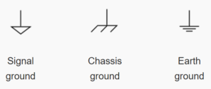
Most of these components have no true main earth ground. Which is, it itself something entirely different anyway. My understanding is that the indicators are as follows:
But on the back of all these amps it labels “Signal Ground” with the Chassis Ground mark. Having never bothered using them I’ve never given it much thought since all my main systems are Naim systems and signal grounding is pretty much taken care of at the source.
Every manual I have simply indicates this terminal as something like “Signal Ground terminator if required for connecting to another device.” which seems a bit vague to me. So in a non Naim context, when and how would this get correctly used?
No guesses please. I can do that myself.
I can say that my non educated guess is that a device with a Signal Ground mark terminal would connect to the Chassic Ground or Earth Ground mark terminal on a device that provides that.
I should add that when you buy certain interconnects like Audio Technica coaxial digital interconnect, at one end there is often a earth trail ending in a spade termination. But this has always been at the source end of the cable.
So I’m still none the wiser. So I am just confused as hell as why so many amps have this; what it is really used for; and why it is always called “Signal Ground” but with a Chassis Ground mark?
From what I have seen, every amp made in Japan has this. At least every Denon, Onkyo, or Yamaha amp I have ever owned. But I see it on the back of high end Japanese amps too even on the power amps.
And the manuals say nothing. I was hoping some of the electrical engineers on the forum would have some idea.
Indeed, a small capacitor is also often used in parallel with the ground lift resistor, to reduce the impedance to ground for very high frequencies (RF).
Typical values can be 100 ohm lift resistor in parallel with say a 10nF capacitor.
The resistor effectively makes the ground induction loop too lossy, so no effective induced current is generated in the earth loop.
Signal ground is effectively the 0volt reference. This can be decoupled from the chassis ground. That is in some designs it is not necessary to have the 0volt reference and chassis ground linked.
Chassis ground and Safety Earth are usually linked for safety reasons. An exception are double insulted devices. These won’t have an earth connection in the mains lead and are devoted by a square within a square symbol on the specification plate.
Thank you to both. I appreciate that. But I’m still wondering, if you had a system with these terminals on the back of everything, exactly what would you do? Pick one device as the signal ground? Daisy chain them?
And is the label and mark inconsistency effectively saying “connect a signal ground out from a device or interconnect that has it, and this terminal will ground it to chassis”?
It depends on the device and how it’s designed.
For example if the device uses a method of lifting the ground for each input, then it will not matter whether the Connections/inputs to are chassis signal grounded or not…
Yes, I am working on the assumption that a device actually provides an intentional Signal Ground out connector. Which I have seen on the back of a couple high end CD players here.
In that situation, assuming you had signal ground to chassis terminals on a preamp and also a power amp, you’d chose just one as the signal ground point and connect them up to that source?
Whatever it is will no doubt result - if effectively implemented - in lower noise floor and more inky blacks.
As well as having your own personal utility pole in the garden, you can have a massive Earth rod.
Outside of flippant speculation, this is my best guess. Sorry.
Yes you would choose one or the other, otherwise there is a likelihood you will create an induction loop and superimpose mains frequency hum or noise onto the signal.