Exploring Mains Polarity on Continental European Naim Systems (with some surprisingly low multimeter readings!)

Hi friends,

I’m not sure if anyone has shared their experience with mains polarity on a Continental European Naim-based setup recently, but I’ve been focusing on this over the last few days and decided to systematically check and reconnect all of my power cables.

I haven’t sat down for a clinical, critical listening session yet, so I can’t speak to the definitive sonic differences quite yet, but I would love to hear your thoughts and experiences on this.

For context, my system consists of:

  • Source: Naim NDX 2 / Naim 555 PS DR

  • Amplification: Naim Supernait 3 / Naim HiCap DR

  • Analogue: Rega Planar 8 / Dynavector XX-2A / Pro-Ject Phono Box RS2 & Power Box RS2 Phono

  • Headphones: LAiV Harmony HP2A & Hifiman HE1000se

  • Speakers: Focal Kanta 2

  • Mains Block: Chord Company PowerHAUS P6

I used a Kaiweets KM602 smart multimeter to take the measurements. The measurement process itself is a bit of a journey (which I’m happy to write up in detail if anyone is interested!), but the results speak for themselves.

Before optimising the polarity, my overall chassis-to-ground leakage reading was sitting around 1.0V AC, which is notably high. After systematically flipping and matching the polarity on the plugs, I managed to bring the total combined reading down to a incredibly stable 0.120V AC.

Given how sensitive Naim’s star-earthing philosophy is to stray ground currents, getting the leakage voltage down to nearly zero feels like a massive win on paper.

In the end, I think this is an experiment absolutely everyone should try. It costs next to nothing but time, and the numbers show it definitely makes a measurable difference.

Have any of you gone down this rabbit hole? Did you notice a blacker background or better transient presentation once you got the leakage voltage down?

Cheers!

1 Like

Hello,
thanks for your post. I, for one, find it very interesting.
Are you talking about something different from simply checking the polarity of the mains cords with this?

Does it not seem odd that apparently some of your mains leads were incorrectly wired in the first place?

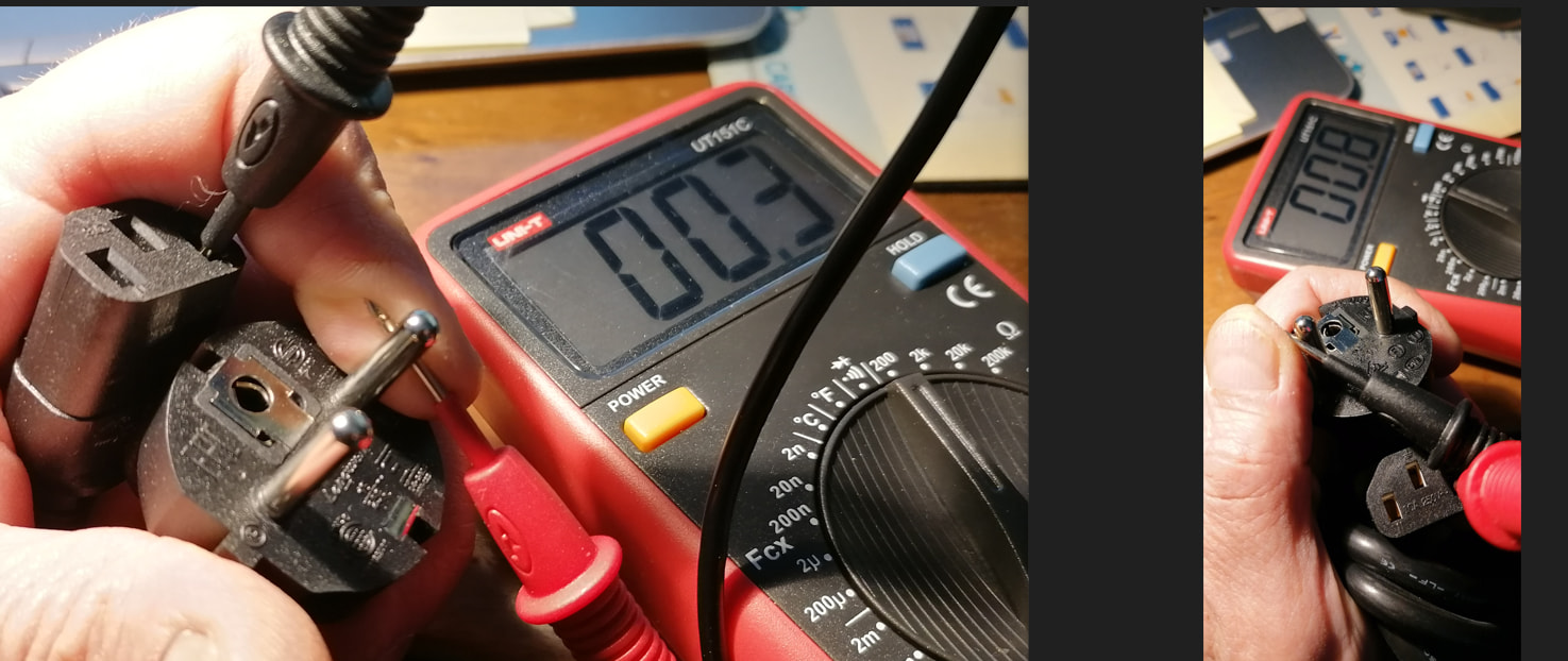
Actually this is more advanced methodology. I put the image below. It is helping you to really measure the chassis to ground leak. Based of my readings before doing it, it is helping to measure the quality of your grounding, power stability, etc…

Well I never checked polarity before. Just plugged my power cables.

so some were wired in reverse?

Yes, it looks like almost all of them.

Thanks. How do you practically measure chassis to ground leak?

Here I am sharing all the step by step guide:

Here is a comprehensive, step-by-step guide tailored for hifi forums. It outlines exactly how to measure chassis stray voltage and identify the optimal AC mains plug orientation for audio components using a digital multimeter (DMM).

Guide: How to Optimize Hifi Component AC Plug Orientation Using Chassis Stray Voltage

Introduction & Theory

Every hifi component with a power transformer leaks a microscopic amount of stray alternating current (AC) voltage onto its metal chassis due to parasitic capacitance between the transformer windings and the enclosure.

By measuring this stray voltage against a clean, external mains earth reference, you can determine the optimal orientation for unpolarized AC plugs (like Schuko). The correct orientation is the one that yields the lowest chassis voltage, resulting in a lower noise floor, better dynamic range, and less digital “glare” or harshness.

Prerequisites & Equipment

  • A Digital Multimeter (DMM): Capable of measuring low AC Volts manually (e.g., Kaiweets KM602 or similar).

  • A Known Good Mains Earth Reference: A nearby, empty wall socket whose outer metal grounding clips are verified and connected to your home’s earth infrastructure.

Step 0: The Baseline Reference (Mains & Earth Verification)

Before touching any hifi equipment, you must establish a reliable ground reference and verify your wall outlet’s wiring topology.

  1. Set your DMM to Manual AC Voltage mode (V~ or VAC).

  2. Locate a completely empty wall outlet near your hifi setup.

  3. Find the Live/Hot conductor: Firmly press the Black probe against the outer exposed metal grounding clip of the outlet. Insert the Red probe into the left slot, then the right slot.

    • If you are on a standard Monophase system (Phase + Neutral): One slot will read full mains voltage (e.g., 230\text{V}), and the other will read a very low voltage (e.g., 1\text{V} - 4\text{V}, which is the Neutral-to-Earth voltage drop). The high-voltage slot is your Live/Hot line. Mark it.

    • If you are on a Balanced/Bi-phasic system (Phase + Phase): Both slots will read roughly equal split voltage relative to earth (e.g., 115\text{V} and 115\text{V}).

  4. Test Total Line Voltage: Insert the Black probe into the left slot and the Red probe into the right slot (bypassing the earth clip). It should read your full nominal mains power (e.g., 230\text{V}).

Step 1: Isolating the First Component

To prevent stray voltages from bleeding between components through interconnects, you must measure each piece of gear in complete isolation.

  1. Turn off your entire system.

  2. Disconnect ALL interconnects (RCA, XLR, DIN, digital coaxial, optical, etc.) from the component you want to measure (e.g., your source or integrated amplifier).

  3. Ensure the component is only connected to your mains power block via its power cable.

  4. Disconnect any network cables (Ethernet/LAN) or grounding wires.

Step 2: Measuring Chassis Stray Voltage (Orientation A)

  1. Plug the isolated component into your mains block. Turn the component’s power switch ON (leave it idling, no music playing).

  2. Set your DMM to Manual AC Voltage mode (V~).

  3. Take the Black probe and press it firmly against the outer metal grounding clip of the separate, empty wall outlet you verified in Step 0. This is your clean, absolute zero-volt earth reference.

  4. Take the Red probe and touch a bare, unpainted metal surface on the chassis of the component under test. Ideal spots include an unpainted chassis screw, an outer ground terminal ring, or the outer metal sleeve of an unused RCA jack.

  5. Note the AC voltage reading on the screen. Let’s call this Reading A (it typically ranges anywhere from 0.1\text{V} to over 50\text{V} depending on the gear’s power supply design).

Step 3: Measuring Chassis Stray Voltage (Orientation B)

  1. Turn the component’s power switch OFF.

  2. Unplug its AC power cord from the mains block, rotate the plug 180 degrees, and plug it back in.

  3. Turn the component’s power switch back ON.

  4. Keeping the Black probe anchored to your external wall earth reference, touch the Red probe back to the exact same bare metal spot on the component’s chassis.

  5. Note the AC voltage reading. Let’s call this Reading B.

Step 4: Selecting the Optimal Orientation

  1. Compare Reading A and Reading B.

  2. The plug orientation that produces the lowest voltage reading is the electrically correct phase alignment for that specific transformer.

  3. Turn off the component, keep the plug in that lowest-voltage orientation, and mark the top of the plug with a piece of tape or a marker so you can easily reference it in the future.

Step 5: Repeating for Remaining Components

  1. Turn off and unplug the component you just finished calibrating.

  2. Move on to the next component in your rack (DAC, Phono stage, Preamp, Power supply).

  3. Repeat Steps 1 through 4 for every single piece of gear individually, ensuring they remain completely disconnected from one another via interconnects during their respective measurements.

Step 6: Final Global System Verification

Once every individual plug has been optimized and marked, it is time to rebuild the system and check the collective electrical health of the setup.

  1. Plug all components back into your mains distributor using their optimized plug orientations.

  2. Reconnect all audio interconnects, speaker cables, and system grounding wires.

  3. Power up the entire system as you would for a normal listening session.

  4. Keep your DMM in Manual AC Voltage mode (V~).

  5. Anchor the Black probe to the external wall outlet’s earth clip.

  6. Touch the Red probe to the chassis ground terminal or an unpainted screw of your central amplifier or preamplifier.

Interpreting the Final Global Result:

  • 0.00\text{V} - 0.5\text{V} (Millivolt range): Outstanding results. Your components’ transformers are perfectly aligned, meaning minimal potential difference between chassis and minimal inter-component noise currents running through your audio cables.

  • 1\text{V} - 5\text{V}: Perfectly acceptable and safe for complex multi-component systems.

  • 10\text{V} or higher: Indicates that one component’s phase might still be inverted, or an un-optimized peripheral device (like a network switch power supply or computer sharing the audio line) is dumping heavy noise onto the system ground.


rewiring polarity on mains leads seems like an unsafe occupation, particularly when it’s more than likely completely unnecessary.

UK & Ireland users please note that this thread is about European Type C, Type E and Type F plugs and sockets that can be wired or rotated in use without regard to Live and Neutral polarity.

If you are in UK/Ire with Type G plugs and sockets (British Standard BS 1363) this thread does not apply to you.

@Richard.Dane
Maybe best it the thread title is changed to reflect this.

10 Likes

ah I wondered that, fair enough

2 Likes

@Mike-B
Thanks for that clarity I was sitting here wondering how. :thinking:

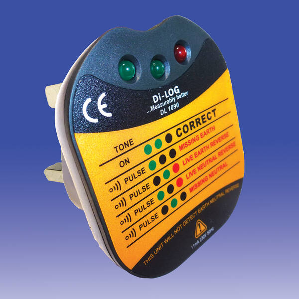
It’s certainly not unheard of for the odd mains socket to be wired with reversed polarity, in the UK, Europe or anywhere else. It’s very simple to check this, and a simple plug-in tester will do the job safely and easily with no electrical expertise required.

Something like this will do the job, and is easily and cheaply available online. It also measures earth leakage, and Voltage which is an increasingly common problem since rooftop solar began to proliferate.

2 Likes

I would NOT advise anyone to attempt this unless they really understand what they are doing, and have well insulated multimeter cables/probes - and in Britain it would not be quite so easy due to the shuttered live and neutral holes in the plug socket. I don’t know about other countries, but in Britain for about £10-£15 you can readily buy a simple plug-in mains checker that instantly and completely safely tells you if live and neutral are correctly wired to the socket, e.g.

There are also more sophisticated ones that do more, but this is likely to be adequate for the intended use here.

Edit: I wrote this immediately upon reading the OP’s second post, before seeing others have posted similar.

1 Like

PLEASE NOTE; this thread refers only to Continental European mains (NOT UK mains !) where they use European Type C, Type E, and Type F (Schuko) plugs and sockets that can be whether wired or reversed. I have edited the thread title accordingly.

FWIW, all you need do is check for the live pin with an induction pen, which is more convenient and potentially safer than using probes or screwdriver types. I would do this as a matter of course whenever demonstrating Naim kit on the European continent and the difference it made could be quite striking, especially in the feel of “life” in the music.

European plugs tend to be wired fairly haphazardly between live and neutral, so don’t assume all are the same. Naim’s old distributor in Germany, Musicline, used to check all the mains leads they would supply with Naim kit and mark the live pin side of the plug with a white dot. The main thing is to ensure that all your kit has the same polarity.

3 Likes

Hello friend,
Naim did already the job for us.If you look at the euro shuko connector on the original naim power cable.You can see there is one pin with 6 or 8 little dots on the housing of the connector,that’s the life/hot side.
The only measurement you have to do with a voltage tester is too find out,wich side on the socket is the live/hot.There you have to put the pin with the little dots on the connector housing.

1 Like

Thanks for the tip.

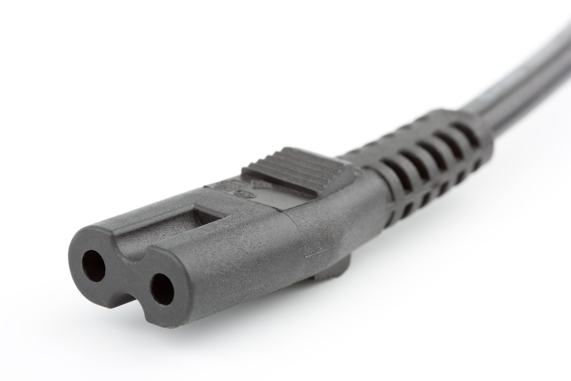
We can benefit in the UK from trying different polarity of the C7 “figure of 8” mains leads on things like Mu-so qb, televisions, etc. this is the connector I’m referring to (photo from Wikipedia)

My 1980s Sony CD player actually has a white mark on the back for matching with the lead and the manual states that optimum performance will be had in that orientation.

There is a difference, but only when the player is switched off! The leakage current from chassis to earth is slightly higher if you don’t follow the recommendation.

Hi to All, relate to the main argument, checking EU (IT,F,D …) prewired AC cords, i have found different connections in some on them …. i cannot find any information or description on the matter.

i was quite sure that they should be all identical, iec have a standard, …. but “french” shucko ? :thinking: