FM Radio Reception Improvement

This is F.Y.I. for FM radio forum’ites ……

I’ve now finished a cleanup of TV and FM stuff
TV first, after the 2022 clearance for 5G, the old attic mounted Group W log periodic & its LTE filter is replaced with a Group K log periodic.
Sony says 100% signal & quality.

My FM reception is via an attic mounted Ron Smith G14 that’s pointing at midpoint between the line-of-sight heading to the main regional transmitter and the hill-shadowed heading to the low power local transmitter. This is over a beamwidth that exceeds the 55 degree acceptance angle of the G14.

The signal from the main regional 46kW transmitter at only 5.6km distance is strong and faultless, the problem is with the local 0.3kW transmitter with low signal levels giving poor SQ and intermittent stereo breakup.

What to do ??? thinking caps on and experimental mode engaged …. Ron Smith Galaxies, and many/most other FM aerials don’t include a balun as its judged that with a reasonable dipole to coax impedance match they operate to an acceptable level without a balun. However, without a balun, the coaxial outer shield becomes an unwanted extension of the antenna, carries common-mode current & less than optimal efficiency.

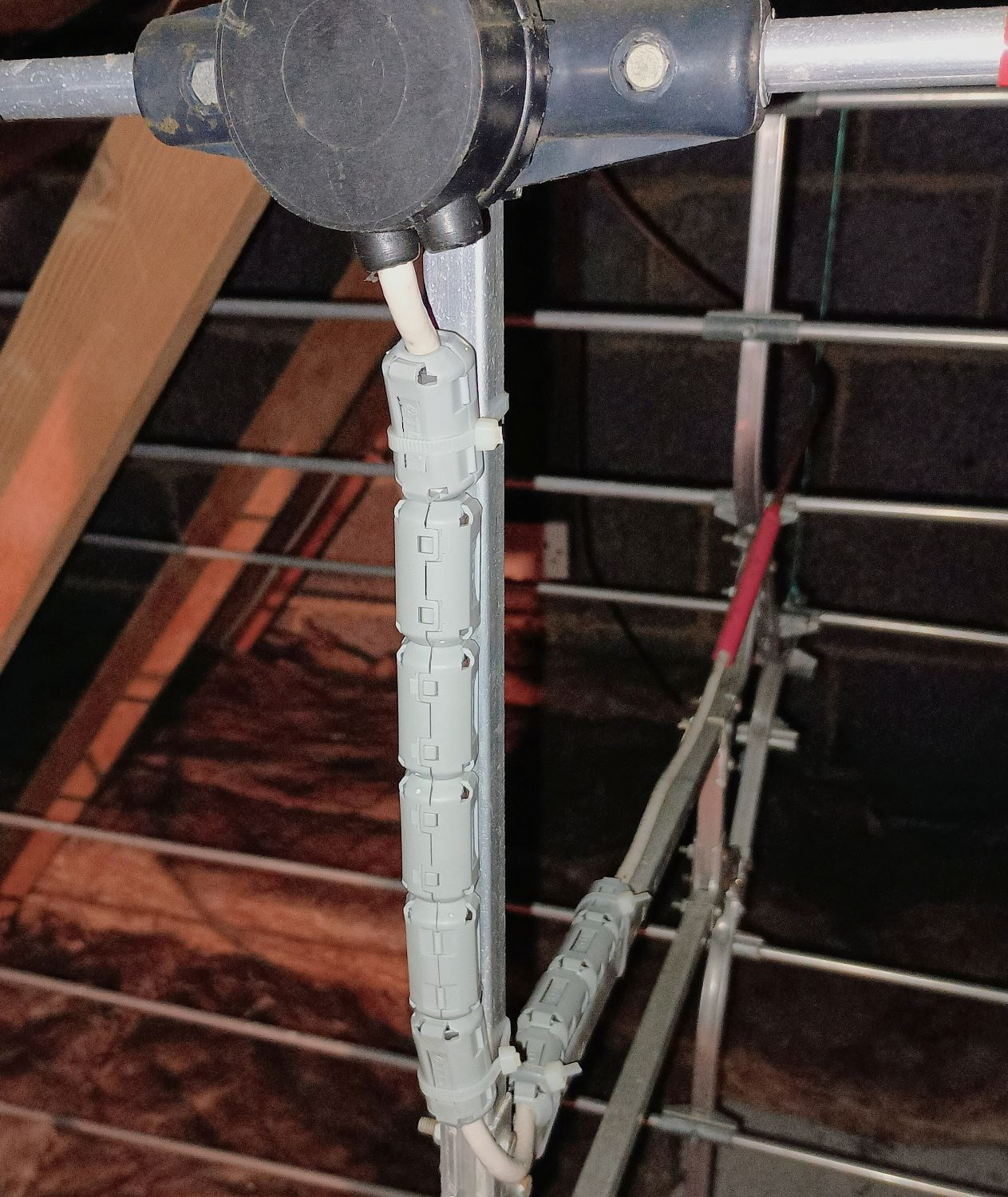
So maybe a balun experiment … I looked up the candidates for a 1:1 balun/choke and selected, made and installed a ferrite sleeve choke known as a Maxwell W2DU. This creates a high-impedance interface between antenna and coax shield & forces current at the antenna terminals to be equal in magnitude & opposite in phase giving the antenna balance and symmetry.

Despite the wide beamwidth and installed in the attic, it delivers an exellent signal from the powerful regional transmitter, and with the Maxwell choke installed, the low power signal from the local transmitter is now very listenable with near-full quieting, no audible hiss and no uninterrupted stereo.


Not easy for you folks with outside aerials, but if yours in in the attic, maybe something to think about.
I just wish I hadn’t sold off my old signal strength meter and was able to get some real numbers.

13 Likes

I will have to give this a try as my current reception issues are self-inflicted by a relocation. I used to live 4 miles from the Sutton Coldfield mast (you could get FM without any aerial on some tuners!)

I’m now living in west Cumbria and the NAT 02 is struggling. I can’t have an outdoor aerial due to the area so have a 5 element dipole in the loft which just about gets the local FM relay although the best signal has been found with the dipole at a 45 degree slant - makes little sense to me but it works.

A further issue I’ve found this weekend is the “birdies” disappear when I take the Ethernet cable out the back of my ND5 XS2. This only affects the NAT 02 and not my Denon 560L but is another bug to iron out.

2 Likes

A question. How much influence does the water tank and pipework in the loft have on the signal collected by your loft mounted aerial?

I have opted for a five element dipole on a pole outside the house, above roof apex level. Fortunately, the Rowridge transmitter on the Isle of Wight is a very strong one so I get good FM reception all year round. Rowridge is about 32 miles away and I am fortunate to live up on the downs north of Winchester. In the summer, I can pick up FM stations from the North of France (in mono).

1 Like

Everything metal for sure and most non-metal will have an effect on aerial performance. It can be minimised with distance and position/alignment, but whatever an attic mounted aerial will always be sub-optimal.

In my case, a long time ago I rewired (moved) all my attic wiring to run down the roof/attic centre line that just happens to be close to the aerial dipole centre and it’s alignment heading.

Plus when I had a new heating system installed the new cold water and the heating expansion tanks are plastic and they and all the copper pipes are at the far end of the attic and some distance from the G14 at the other.

In my situation it’s all helped with my local transmitters being so close (5.6 and 11 km) but I also listen to a few distant low power stations and can get Sutton Coalfield some 100km distance.

1 Like

Very good. Did you have to buy any special brand of downlead to connect the aerial to your tuner?

No, a ‘special’ coax is not required, just a straightforward high quality cable suitable for the higher frequencies of satellite, making it very suitable for TV and even more so for 88-108MHz of FM radio.

I use Webo WF100.
It has a 1mm copper conductor, foamed polyethylene insulation that is superior to the old ‘cell’ formed PVC, and a double screen of copper foil and copper braid.

1 Like

FM Radio cabling is so much simpler than ethernet cabling to streamers. A quality 75 ohm cable is enough, there is no arguing over whether Shunyata, Audioquest or Chord Company make the best cables for FM radio reception.

1 Like

If the audiophool people ever get interested in radio, then the fancy stuff will appear and the prices will increase exponentially.
It’s the end users that drive this high end cable madness, the vendors just feed off the madness.

3 Likes

Going back to topic, Mike, do you have a signal strength meter on your FM tuner? Do you notice a big difference in signal strength between, say, BBC stations from the same transmitter?

No SSM, my tuner is a NAT05.
As I said in my 1st post …. I just wish I hadn’t sold off my old signal strength meter and was able to get some real numbers.

But I doubt the addition of the choke balun has done anything for signal strength with a change in mV numbers.
I do suspect the very obvious improvement in SQ and stereo performance is because the choke has corrected the mismatch between the balanced antenna and the unbalanced coax and restored symmetry, hence getting the best out of the weak hill-shadowed signal.

+1 for fitting a balun. This helps cut interference and can, say, match a 300 ohm folded dipole to a 75 ohm NAT.

Regarding signal reception, I moved house a while back and my Galaxie 14 wouldn’t fit in the loft. It’s physically big in three dimensions and I really struggled to position it where I need it to point - Rowridge, 39 miles south-ish and over the South Downs. I tried a few flat dipoles (Antiference etc) and eventually came across InnovAntennas in Essex. Their 11 element OP-DES FM antenna is 3.5m long. It just about fits in our loft space and, being flat, is easier to position. It’s been a great success. The NAT01 would often struggle to hold the stereo image but now I get excellent sound quality out of it, very little noise, and no crosstalk. If you’re also in a weak reception area it may be worth your while checking them out.

1 Like

I’ve seen them around, but note they have a 50ohm impedance so need a balun to connect with a 75ohm coax and NAT input.
How did you handle that?

That’s only relevant for a bare folded dipole, the impedance lowers significantly when director(s) and a reflector are included. The actual impedance is impossible to calculate as it changes with inter element spacing, it can only be determined thru testing, but it does reduce significantly.

The antenna spec says the feed impedance is 75 Ohm or 50 Ohm so suitable for my NAT01, I believe. When it came to choosing a balun, I ask them about that and they said a 1:1 balun would be fine - “These are typically 75Ohm for receivers. If feeding with 50Ohm, SWR will still be 1.4:1 or there about so perfectly acceptable on either.”

So that’s what I have, and the results are excellent.

That’s helpful to know, thanks. In the light of this, I’d contact the manufacturer to get the actual expected impedance and choose a balun based on that.

I note in their www info they suggest and supply a ferrite choke (1:1 balun)
This is exacly what I have installed on my G14.
InnovA have different names for there chokes, same in principle, universally known as a Maxwell W2DU in the Ham radio world.

1 Like

Another possible issue, for me at least, is using the existing built-in home coax wiring. Ours is getting on 50 years old now. Does it deteriorate with age? Has coax technology significantly improved since the 70s?

Also the wiring splices together FM and UHF antenna feeds in the loft, via a little circuit box, then splits them out again in the lounge to a dual UHF / FM wall point. Could this be detrimental to the FM signal?

Yes, your coax wiring is well past it’s sell by date and your FM and TV will benefit from a complete replacement.

First it’s not ideal to have splitters, these always have a signal loss, even a top end 2-way loses about 3.5 to 4dB, and with one at each end, it’s double. The supermarket cheapos will loose even more and more than likely don’t work properly anyway.

Re the 50 year old coax, and for sure if built into the house during construction, it will be ‘contract’ VHF TV standard. It will have thin single layer braid with more open space than copper, the core insulation will be PVC with air cell spacers, all adding up to a significant signal loss.
Then … add 50 years and yes it does degrade and your already sub optimal signal loss is even worse.

2 Likes

Thanks. I feared as much. That’s my weekend sorted out, then :slightly_smiling_face:

1 Like

Have fun … See my previous post …

I use Webo WF100.
It has a 1mm copper conductor, foamed polyethylene insulation that is superior to the old ‘cell’ formed PVC, and a double screen of copper foil and copper braid.

2 Likes