Headphone Tube Amp Build

I just started building the Aegis headphone amp that was designed by L0rdGwyn from Head Fi.

As I’ve just started this project, which is essentially a TOTL tube amp with a parts only cost of approx £2k or more, I thought I’d post here to see if there was any interest in following progress? it’s a great project with excellent instructions for those who fancy a go and as someone who has never built an amp before, may inspire others to have a go.

Of course, that’s if it doesn’t break any forum rules etc.

4 Likes

That sounds like a brave thing to undertake and definitely too much of a stretch for my mediocre to moderate soldering skills. I would be interested to follow your progress from time to time though.

Best of luck!

1 Like

Ok… it shouldn’t be a massive thread as there is no point showing every wire, resistor being connected. That would be a little tedious for all involved :joy:. The forums, Head Fi and DIYAudio provide a lot of info including the step by step manual which are at DIYAudio dot com plus files for ordering the PCB boards and a full parts list (Google L0rdGwyn Aegis). This is just about my experience as a first time builder and how I got on.

So, for a 1st post to get this up to date.

Reading the manual from L0rdGwyn is absolutely essential. As well as instructions it contains vital safety routines that must be followed. We are all responsible for our own safety so you cannot skip it. Read and read it again to understand exactly what you are doing should you decide to give it a go…

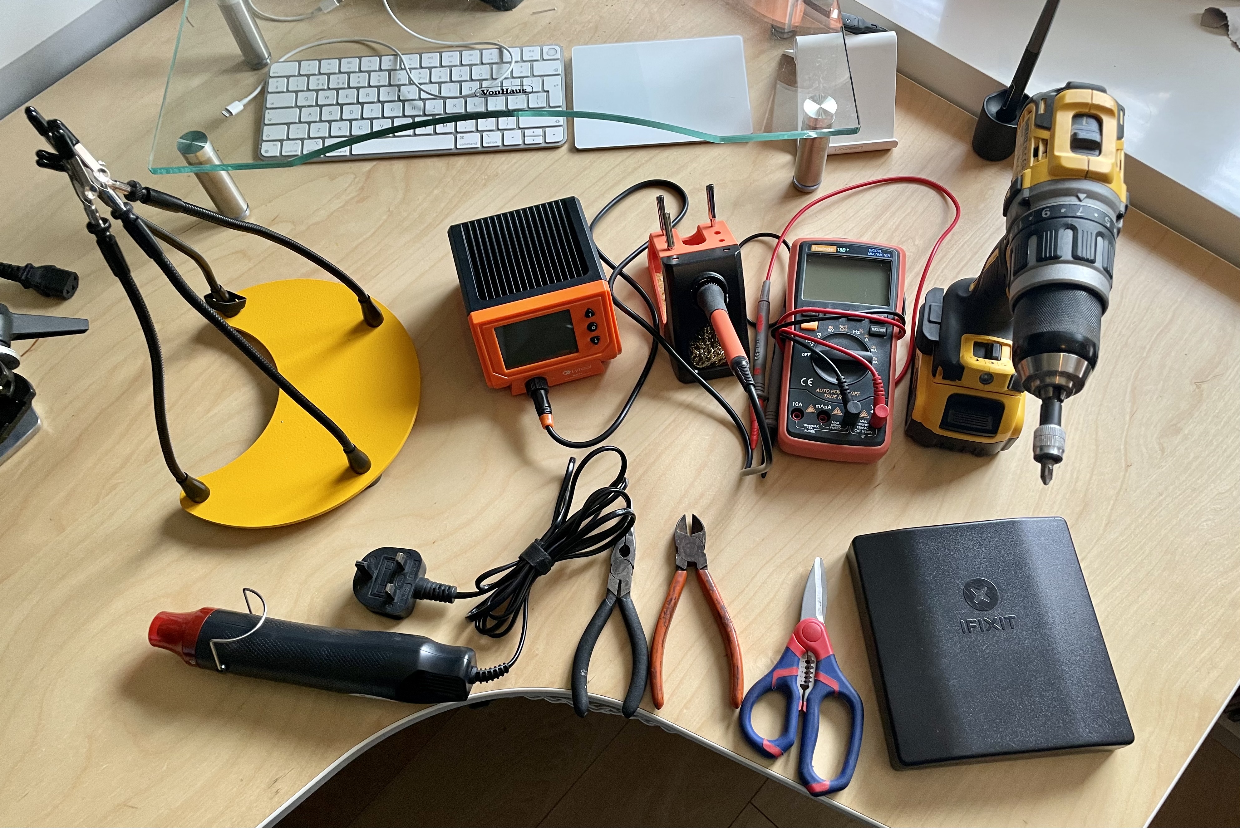
This is the gear needed to make life easier building this. Most I feel is essential.

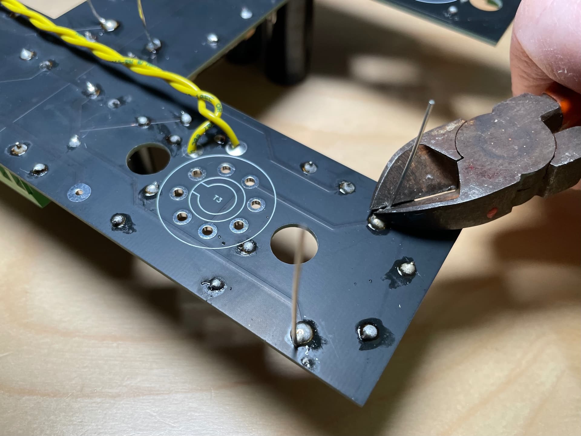
Soldering station, Multimeter, third hand clamping tool, electrician scissors and wire cutters, iFixIt tool set and a hot air blower for cable shrink wrap.

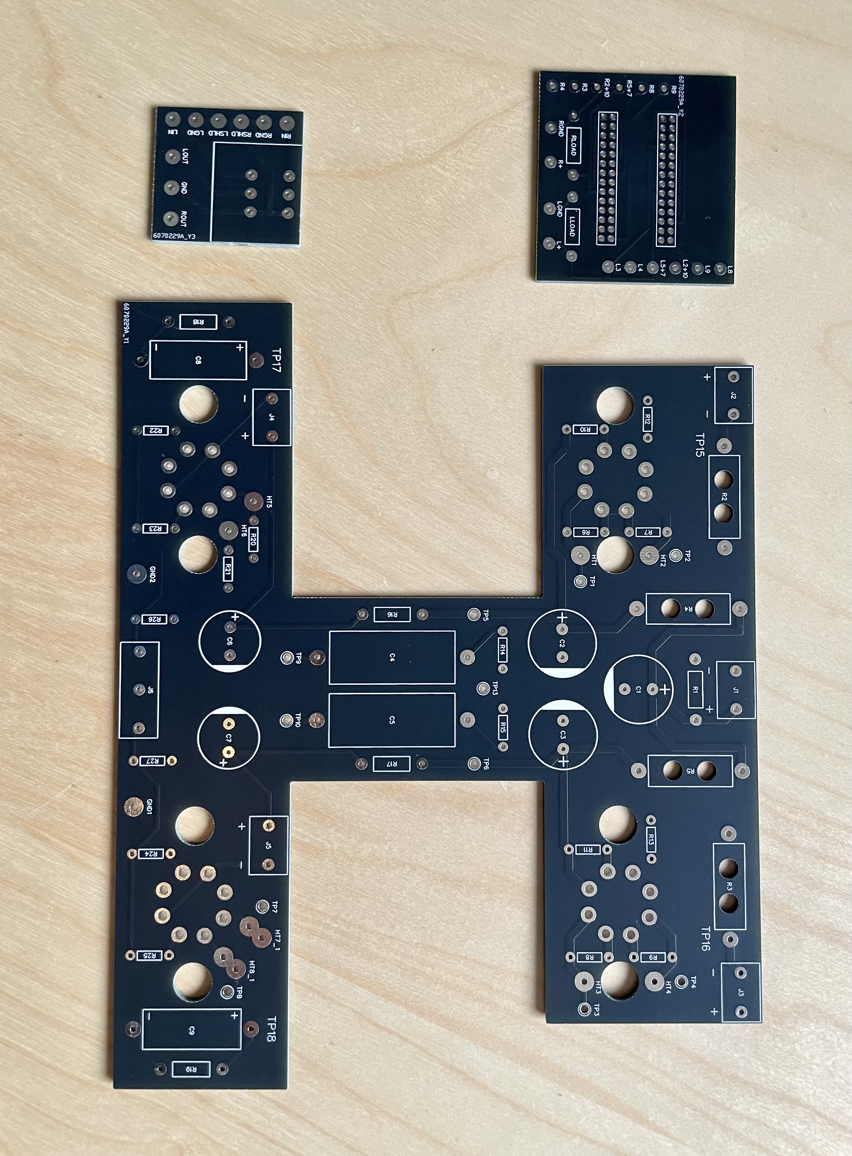
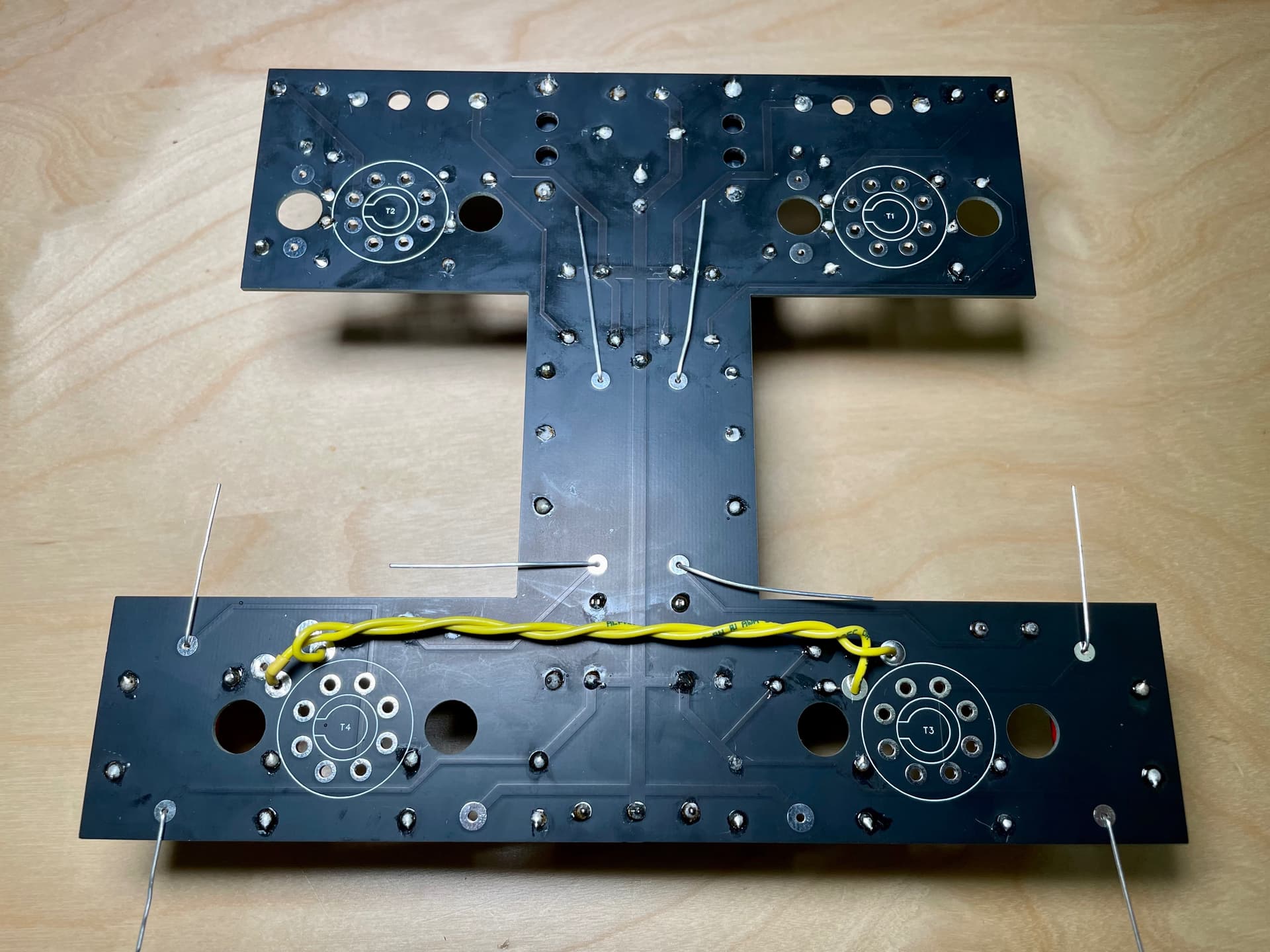
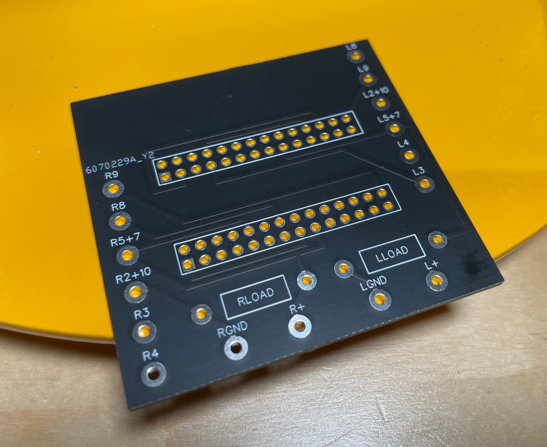
The PCB boards when they arrive look like the photo below. When ordering you have to buy 5 of each but on the forums, there are people selling spares so you can check there first.

So far, parts wise, I’ve received the cabling and resistors etc. Not visually exciting stuff. All 20awg silver coated oxygen free both solid core and stranded.

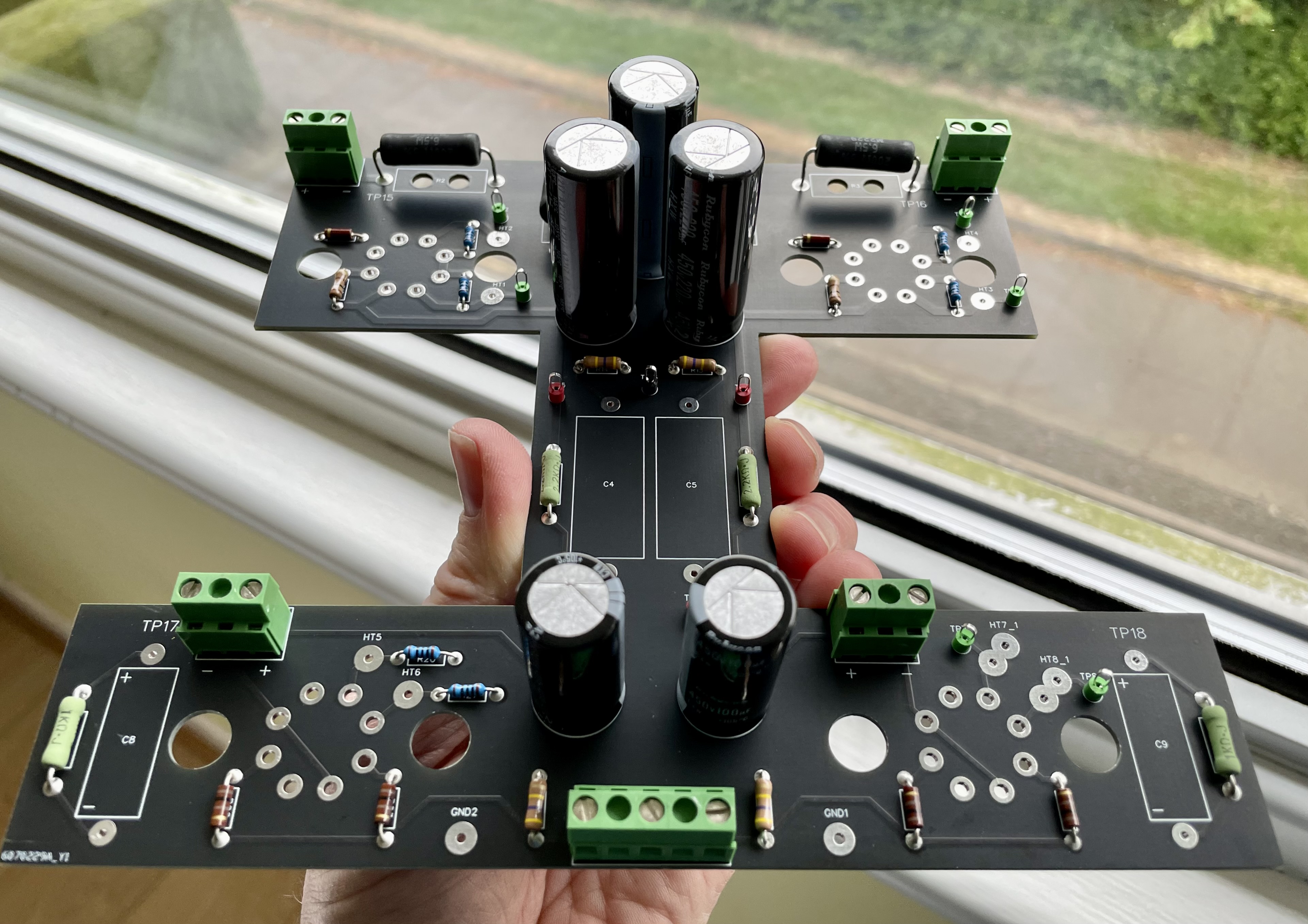
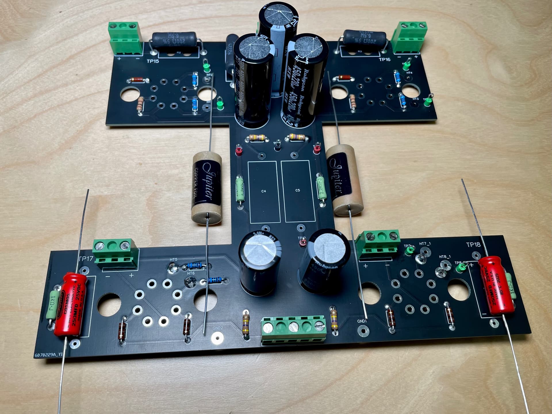
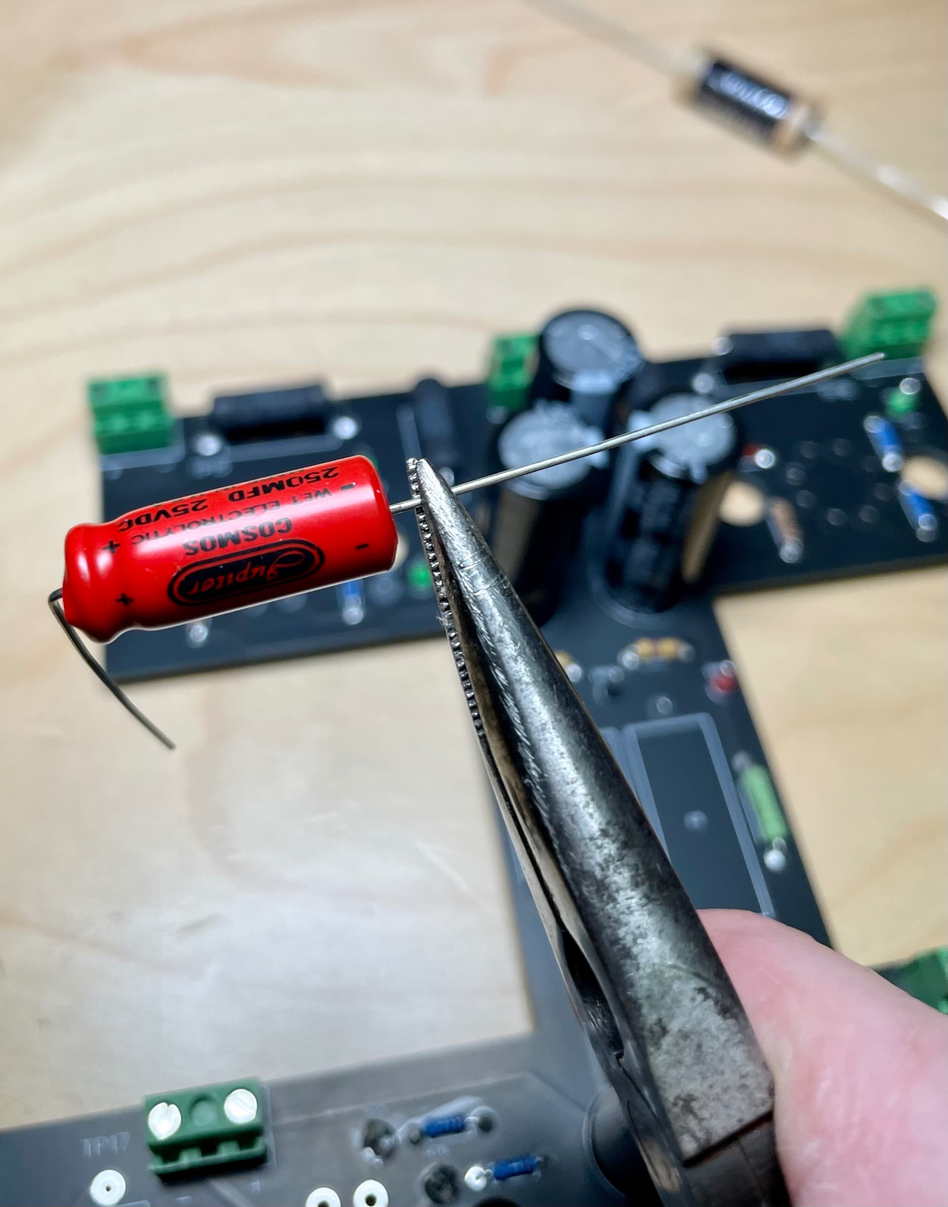
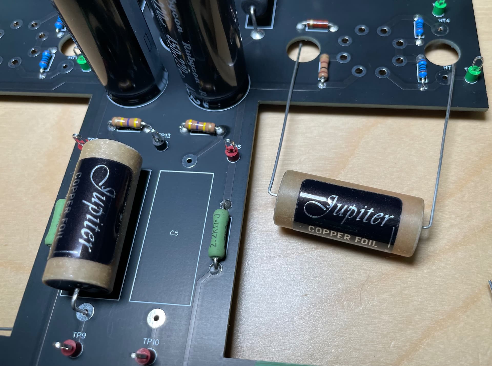
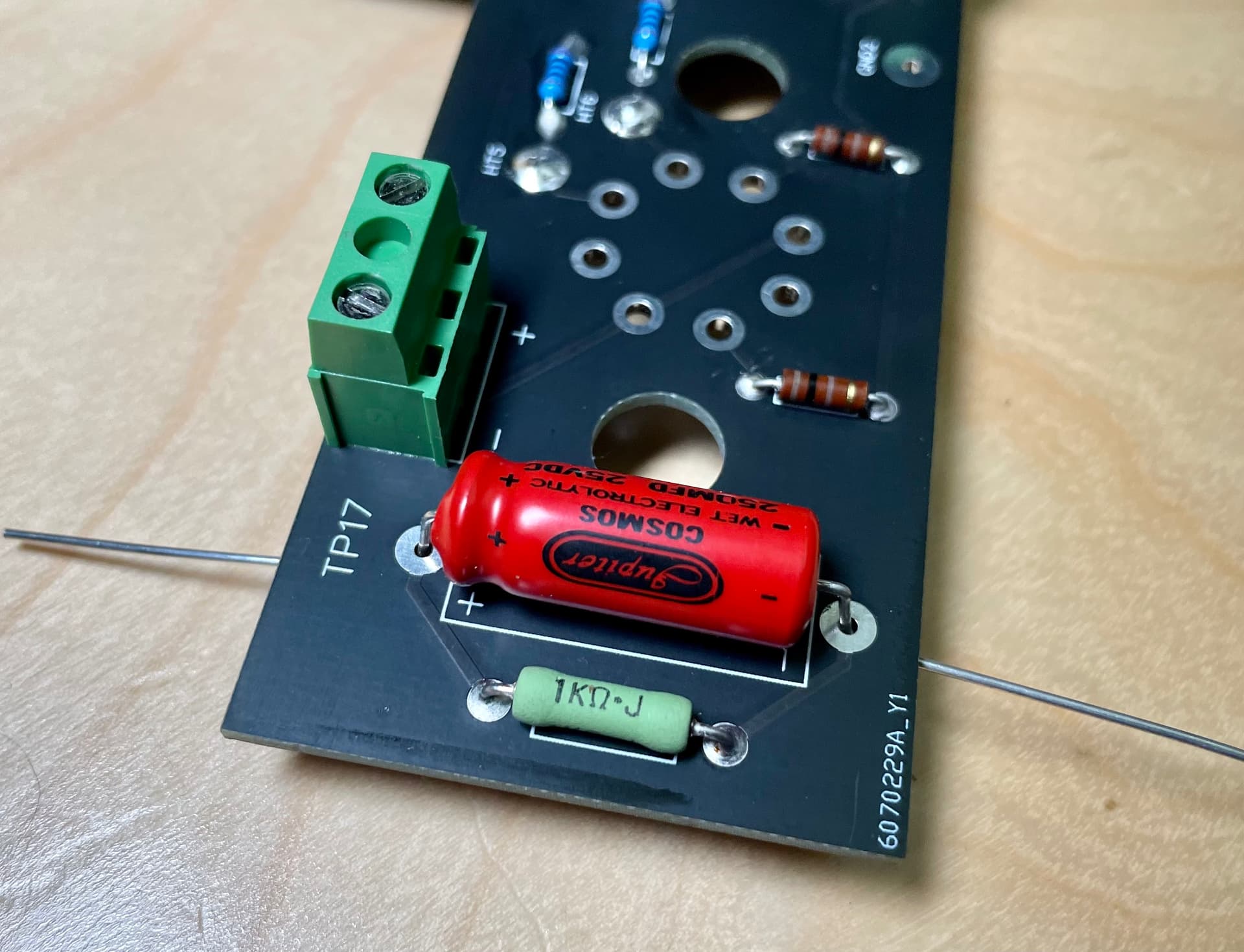
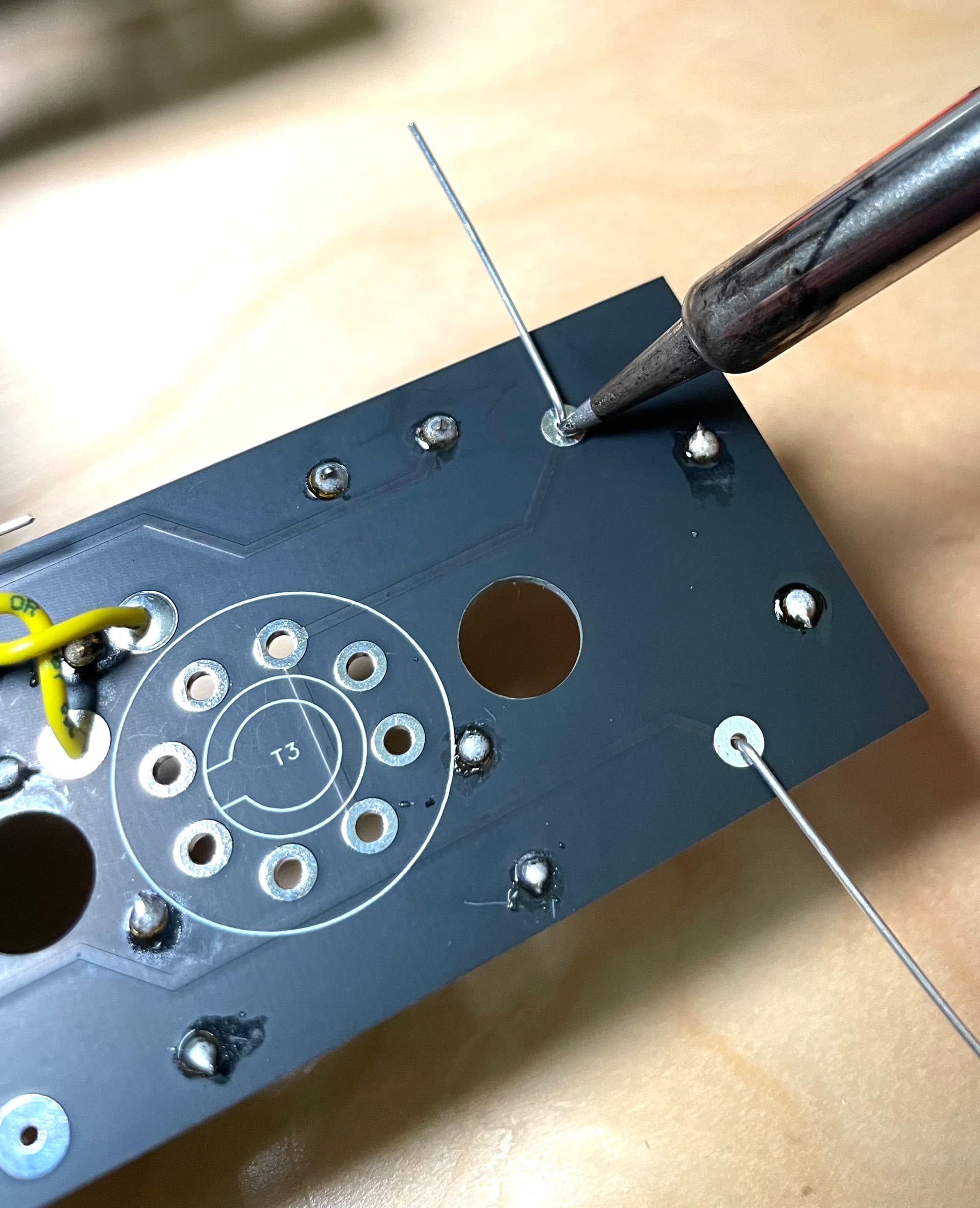
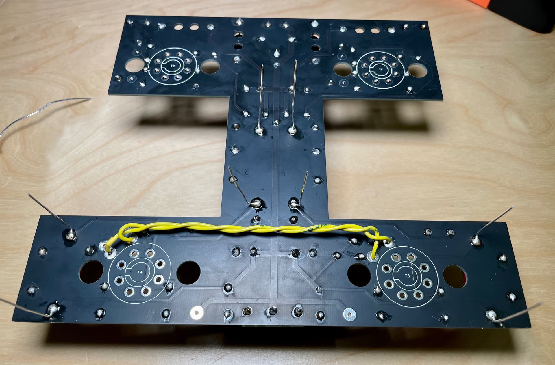
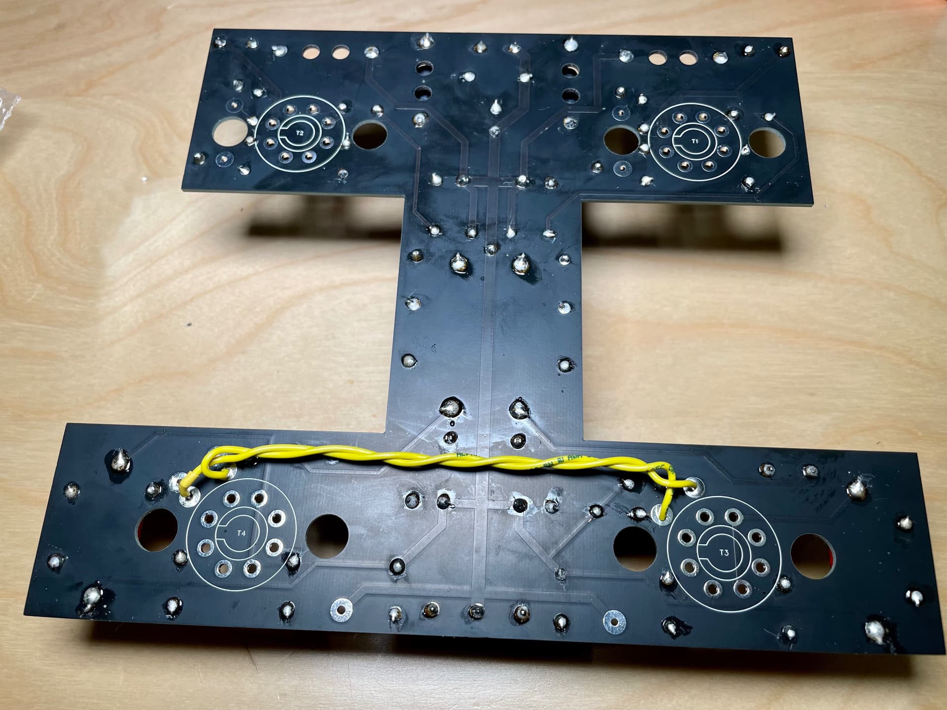
This is where I’m up to with the main board, approx 2hrs work. Just the Jupiter capacitors needed. To be honest, I found it rather relaxing and enjoyable experience. Just took my time and double checked everything. I did practice before hand on a PCB practice kit from Amazon which was cheape and very useful experience!

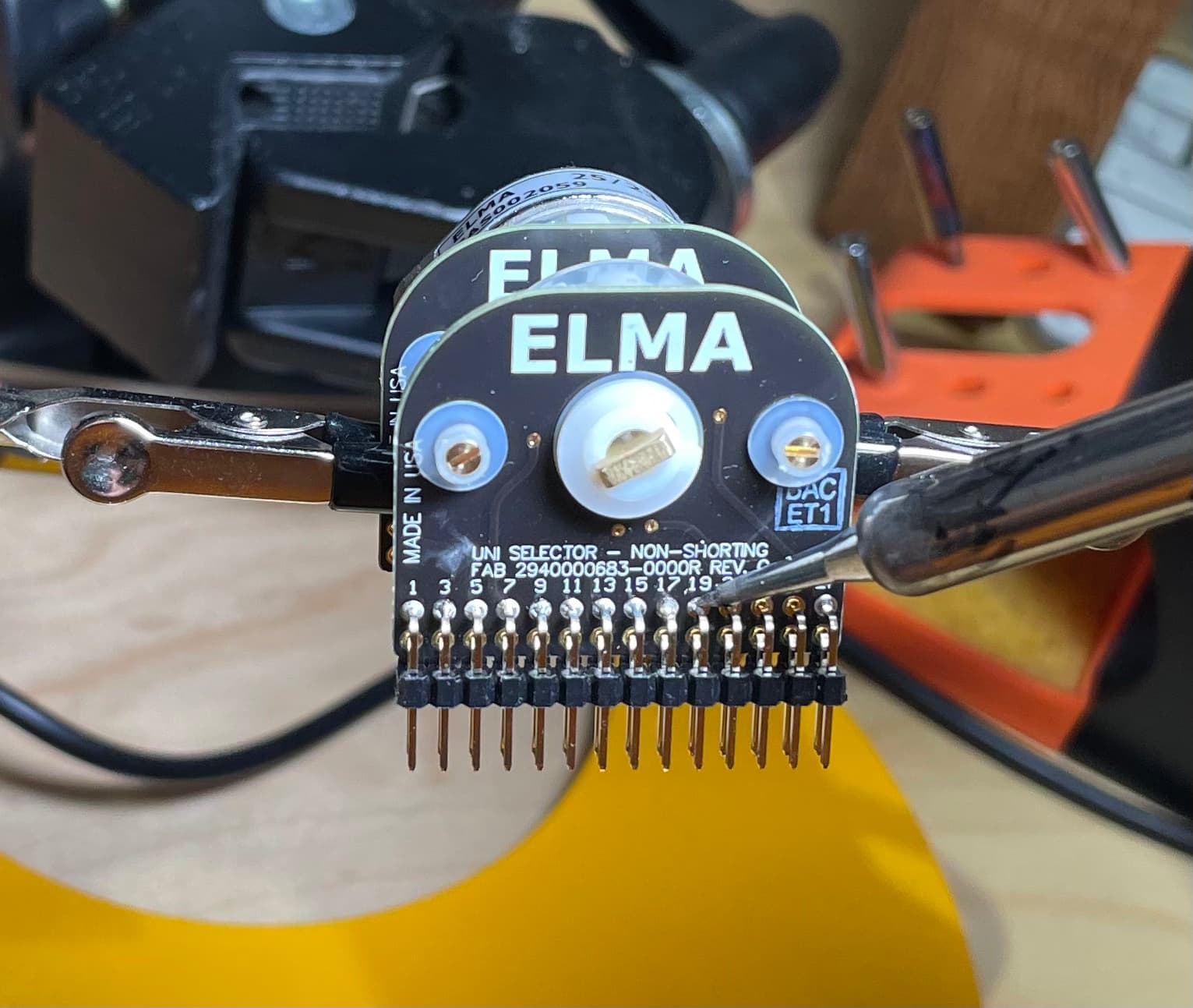
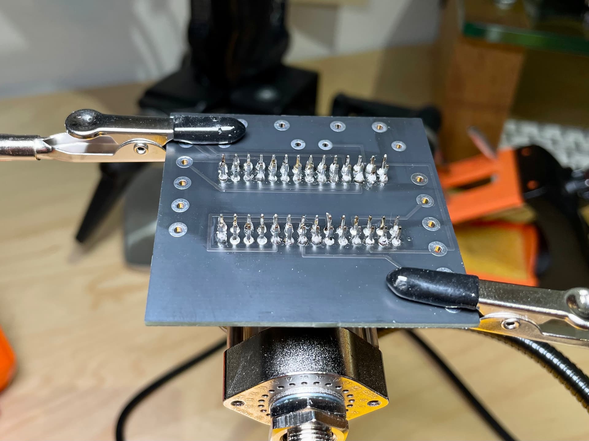
The Alps Blue Velvet volume pot was soldered to its PCB board along with the cables for the RCA sockets and the wires that will connect it to the main PCB board. Extra used so it can be sized perfectly once added to the chassis later.

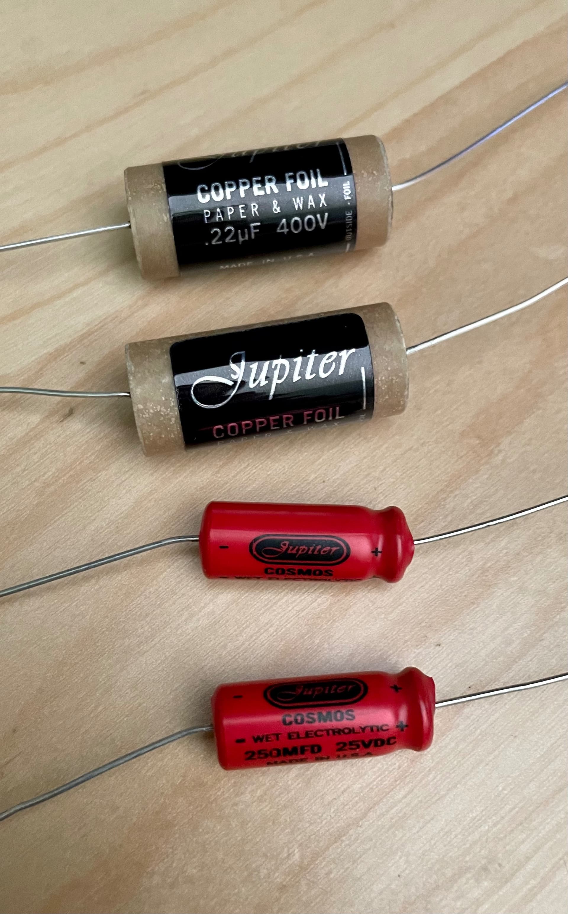
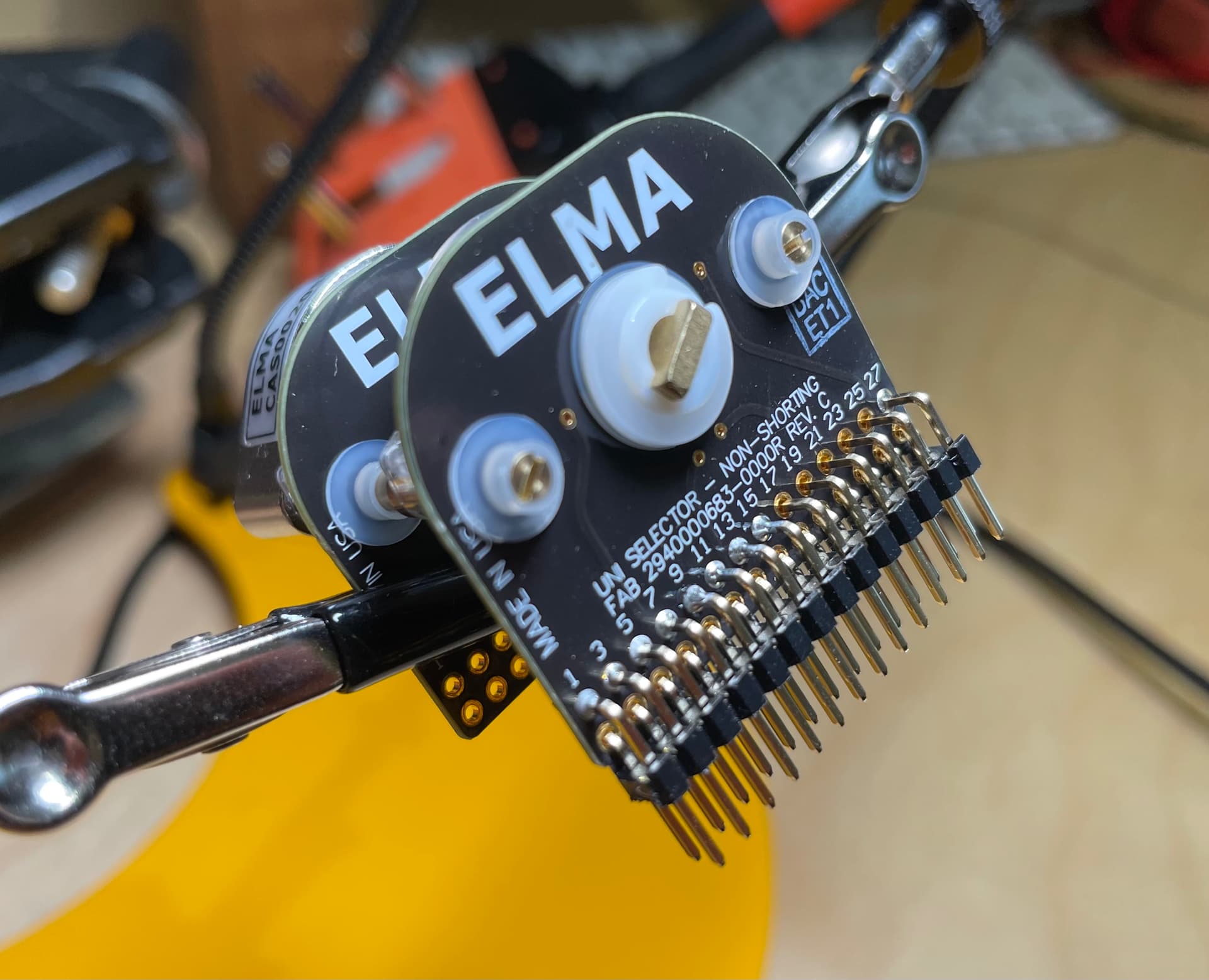
That’s where I’m at for now, waiting on the chassis, 6 Lundahl transformers/Chokes, impedance switch (ELMA) and Jupiter capacitors. The capacitors should arrive next so I can complete the main board.

3 Likes

A-Fin, you are (of course) utterly bonkers to attempt this, but you have my very best wishes!

Do keep us posted.

Will you be making a set of cans when the amp build is completed?

1 Like

Lol …. I wish. I’m intending to add a pair of ZMF Atrium Closed backs to go with my Meze Elites.

Love the sound of tube amps… this’ll be my second one (first I’ve built as a kit).

Very good luck with your project…post some work-in-progress photos.

And have fun!

1 Like

Will do. The Jupiter capacitors should turn up next week so I’ll show the fitting of them. Easier to see them as they’re bigger!

Looks very nicely done so far.

2 Likes

As promised.

Jupiter copper film capacitors and Jupiter Cosmos electrolytic arrived today.

First is to size and position them, especially the Cosmos electrolytic as they have + - orientation. From there you can tell where you’ll need to bend the wire to fit them onto the board.

Once Fitted, you make sure they’re as close as possible to the board and then bend the wires on the other side so they’re held in position. Fit all parts to the board and then turn over ready to solder.

I heat the connection with the soldering iron for a couple of seconds first before applying the solder… this way it draws the solder into the joint.

After they’re all done, bend up the excess wire and trim as close as possible to the board.

This board is done for now. Once I have the transformers and chassis (on order) it’ll be installed and the wiring from the transformers etc soldered to the board plus fitting of various switches, sockets and RCA cables etc. That maybe a few weeks yet though as the chassis and transformers are made to order.

5 Likes

This is great! Thanks for sharing … I know what you mean about the soldering being therapeutic, I found the same when doing the crossovers for my speakers, but this is on a whole different level! :slightly_smiling_face:

Will be following this with interest!

1 Like

Lol. Yeah, there is almost a sense of disappointment when all the parts are in :joy:

Got to hand it to L0rdGwyn though, magnificent effort both in terms of the design, supporting instructions and parts list etc. it’s made it an enjoyable build so far!

2 Likes

Just goes to show, I found building new crossovers a bit stressful and it made me wish I had more patience and better soldering skills. It all worked out well in the end but I wish I’d known about soldering practice kits mentioned earlier.

1 Like

They’re very useful. For about a £10 you get to practice with no pressure!

Also practice with soldering and desoldering rca, plugs etc!

There are very few occasions when I genuinely regret my reduced vision but this is one of them. I would love to be able to use a soldering iron with the beautiful accuracy I’ve seen in various dealers. It fascinates me and, as yourself, I suspect I would find it very therapeutic indeed. Sadly I lack the fine detail so this is something I will never do. Absolutely comfortable with saying I am genuinely jealous.

1 Like

Exactly, my close vision isn’t too bad but I do need to use my reading glasses… I think I’d struggle without them.

I did toy with the idea of buying one of those large magnifying glasses / panels for the finer stuff but I’m ok for now. After this I may look at a Solid State amp and / or a Linear Power Supply.

As a photographer, illustrator you have my sympathies there… I have my fingers crossed to get to retirement before it detritus too much but I would still miss it badly as I love taking photos away from work.

I’m impressed A-Fin by your courage in building this. I look forward to seeing the progress of your build. I debated attempting to build a PC, but chickened out and bought my son a gaming machine some years ago. My eyesight is rubbish now, but I’ve a steady hand. Good luck!

1 Like

I need +1.5 reading glasses so I bought a couple of those cheap £3 ones, +2 and +2.5 for things like this, works great :slightly_smiling_face:

3 Likes

Good idea… may need something like that when I get to soldering the impedance switch :joy:, that’s the hardest bit of soldering!

1 Like

Well, it’s been a little while since the last parts arrived but today, the Elma Impedance Selector switch arrived which meant I could build that section. It consists of the switch, 2x 14pin headers, PCB board and 2x 4.7k resistors.

Once the unit is built, it’s then fitted into the chassis (once it arrives). Then, the two transformers are wired into the PCB board and the output cables to the XLR 4 & 6.35 sockets.

The PCB board prior to install.

One of the two 14 pin headers. These are fiddly to solder to the switch, you definitely need a third hand grip so you can focus on soldering the pins.

A photo part way through soldering the first 14 pin header (28 solder points in total). Not much room in there!

I used a fine tip with the soldering iron and had to rotate it around to try and find the best angle so as not to solder two points together.

Here’s the back of the PCB board showing all 56 solder points.

And, this is the finished board including the two 4.7k resistors. In this photo, the 4 connectors on the left edge are for the XLR /6.35 output. The one at the front is for the left hand transformer, the righthand connection points are out of shot on the other side.

I’ve had notice that the chassis is complete and the painting should be finished this weekend so it shouldn’t be long before it arrives. That will mean a lot of building and installing! Should be fun!!

5 Likes

This is looking great! Fiddly indeed :grinning:

1 Like