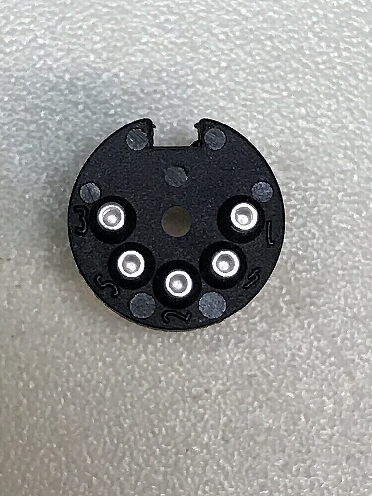
In the post Xmas period, I made up a couple of DIN to RCA adaptors for use in the Headline’s input, using both male and female in-line Preh DIN5’s. I’ll open one up later on to see if mine have numbers on the back.
Edit: They do indeed.
Although I confess that when I made them up, I opened up one of my Headline’s connectors, and taped it to the table in order to provide a visual aid!
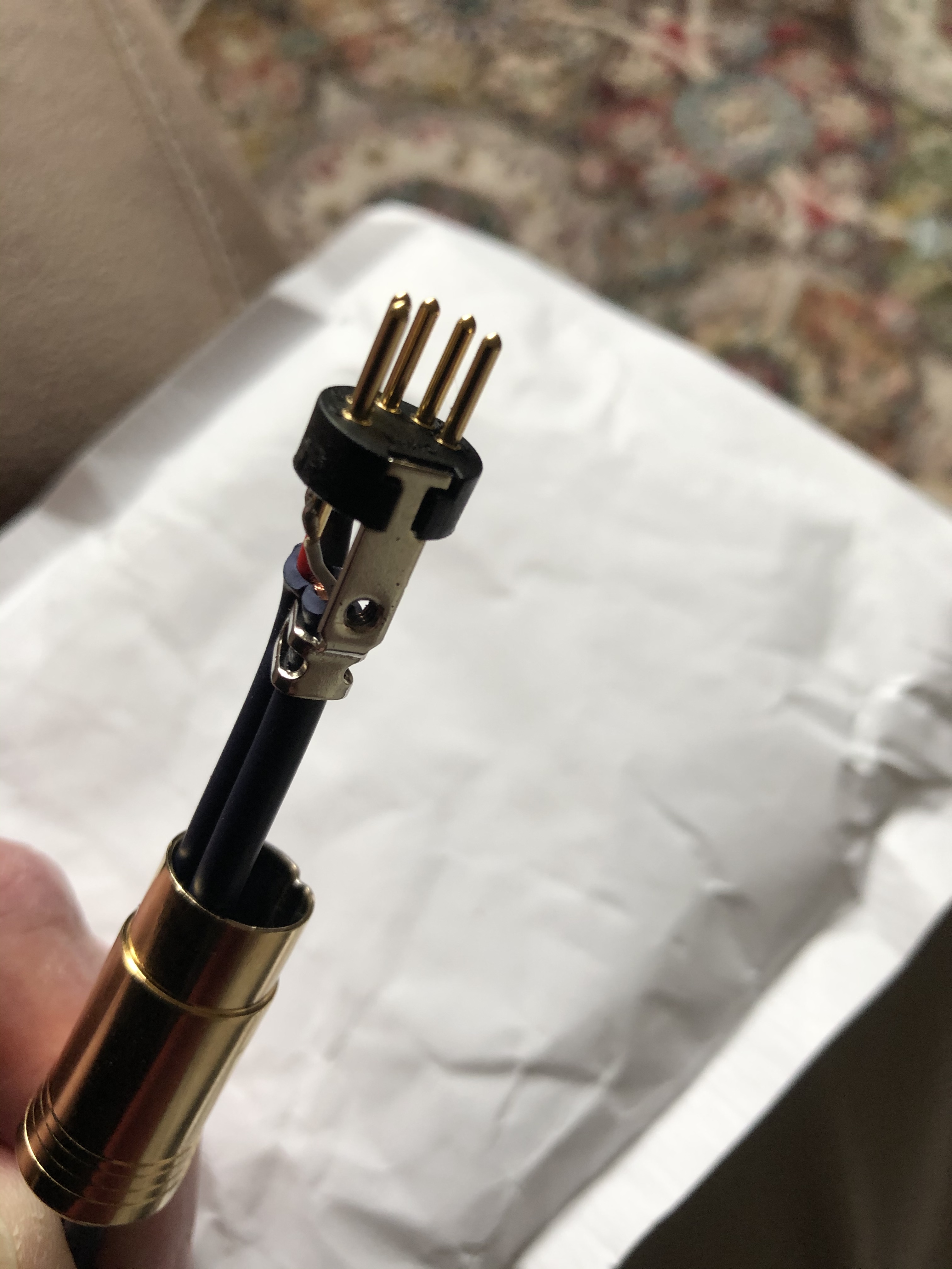
Here is a picture of my 5 pin Din to 2 Phono lead. Its a Chord lead, which was built as a 4 pin Din to 2 Phono (the arrows are correct for this), which I mod’ed to 5 pin (just swapped the pin assy). Soldering was tricky, but I did my best…
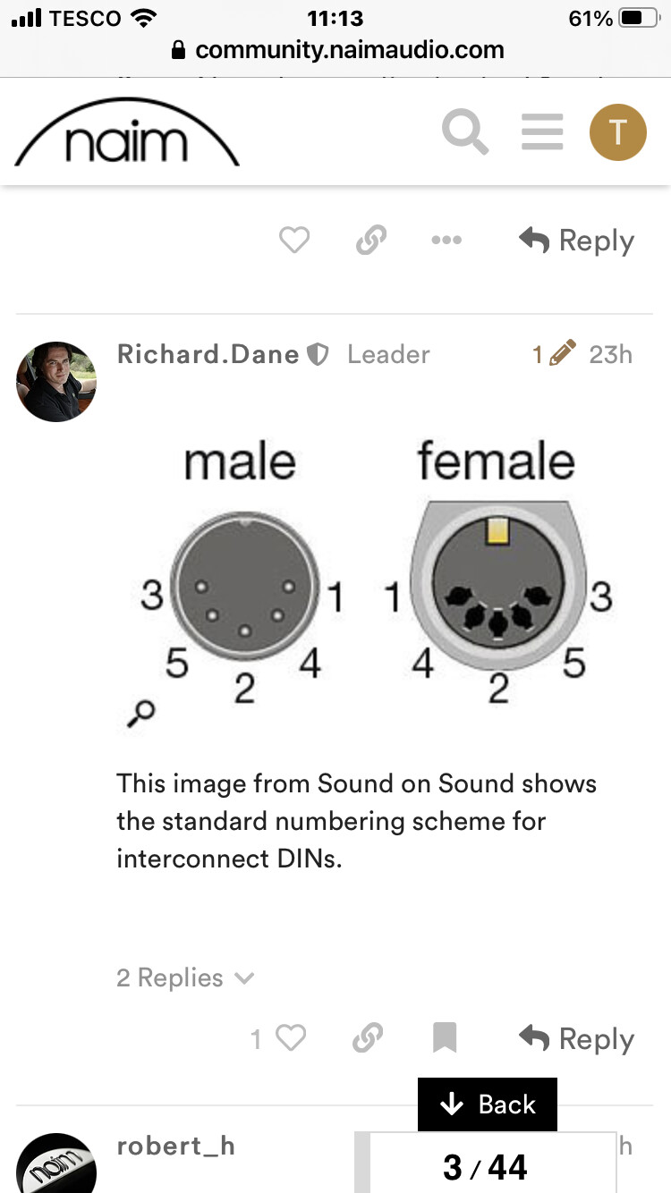
The photo shows how the cable just received and not working is wired. The other photo shows Richards diagram. The male plug seems to me to be wired to pins 1, 4 and 2. The supplier has seen the photo and says it is wired to pins 3, 5 and 2.
IMO, this cable is wired as a Phono -TO - DIN - so its wrong for what you want.
Its visually 3-5-2. Exactly correct as per @Richard.Dane 's picture you show above.
The Male pic will be looking ‘at’ the pins - or ‘at’ the plug - from the front - not from the wire side.
Its simple. If it doesn’t work its wired wrongly. But… YMMV… this is the Internet…
Sorry, but I will give up at this point. Please contact whoever you got the cable from. I hope they will help you, but if you asked for the wrong cable, then maybe not.
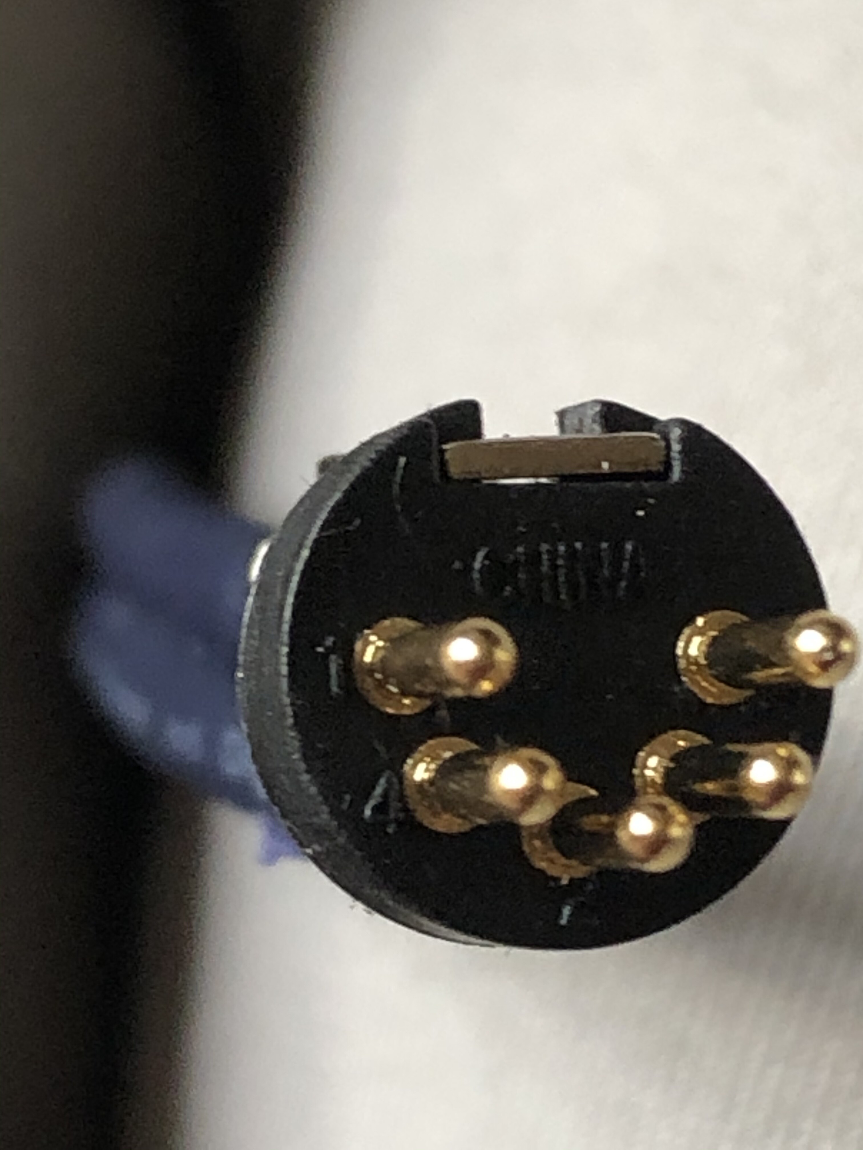
The supplier told me that the male pins are numbered on the front and under high magnification he is right. However the numbers don’t match Richards diagram.
Hi James. I’m really confused by this! If you are right and Richard’s diagram really is the wire side, if you overlay the two diagrams then pins 1 and 4 would be going into sockets 3 and 5. It doesn’t make any sense.
Yes, the image doesn’t elaborate but it looks like it’s the side on which you solder.
I have to say though that if you look around the numbering scheme for the 180 degree DIN does seem to vary, which is quite confusing if you go by the numbers. Easiest is to just go by the diagrams that Naim use on the back of their kit, which show which pins are which on the DIN sockets.
Oh this takes me back to fault-finding broadcast installations when the labour was done “on the cheap”!
Imagine large panels of male and female XLR connectors where working from the solder side, pins 1 and 2 swap relative positions based on connector gender. Solder everything up and same way and half of them would be wrong…
Dies the DIN standard not specify how the pins are numbered?
This appears to what is confusing us.
The photograph that shows the soldering side clearly shows 1,4 and 2 and what you’d solder to. And that aligns with the socket for tape out on the back of Naim pre amps.