Speaker Build - CNO Grande

So this is very long overdue…

I had considered building some speakers since buying my amp and streamer but it was this topic started by @Mark84 that really inspired me to look into it more seriously.

Mark’s CNO4 Build

I had seen the Troels Gravesen site before but hadn’t read it in depth, maybe a little put off by the rather old style of the site! However, even if you’re not considering building speakers I highly recommend you take a look, it’s really interesting to read about the process, what worked, what didn’t and why things are done in certain ways. There’s a lot of knowledge on there.

The other thing I was a bit hesitant about was whether they’d be any good. Then I read how long he’d been designing and building speakers, along with the fact that ScanSpeak use his designs to showcase their top end Ellipticor drivers in their showroom and at HiFi shows and also link to his designs on their driver spec pages, well that’s a pretty good endorsement to say the least!

So then the question was which ones to build? There’s a massive spread of designs there, from compact two ways to gigantic multi driver speakers that would probably bring my house down!

After reading through a lot of the designs I decided on the CNO Grande. It caught my eye because it’s a full three way (ingrained from the late seventies most likely!), four driver design in a slim tower like my current speakers. It uses the Seas Excel drivers and his description of their sound was the deciding factor!

Of course the other question was whether I could actually build them! I’ve not done woodwork since school. I’ve never soldered electronics … unless model railways when I was a kid counts :slightly_smiling_face: so the crossovers were a concern too!
At least I could try building the cabinets before buying the kit (the plans are on the site), and I needed a project to get me on my feet more!

TBC…

Mark

15 Likes

Great news and great intro. I will be looking forward to progress pictures. Can I ask which level of crossover components you went for? I think you made a great speaker choice. I am sure the seas nextel drivers will not disappoint.

Before I could do anything I needed somewhere to work, so the first job was to clear out one end of the garage, took me all weekend and several trips to the tip.

That was followed by building a workbench, something I’ve wished for many times over the years but never got round to.

The top is inch thick plywood and I put up some LED lights above it.


(Pic from a later date)

Ready to start!

Mark

10 Likes

Thanks Mark, I decided on level one … if I’m going to do it … :slightly_smiling_face:

More will be revealed as I go on, I need to catch up to where I am, would’ve been a lot simpler if I’d pulled my finger out and done it as I went but I was having too much fun :slightly_smiling_face:

Cheers,
Mark

1 Like

Reminds me of the ridiculous “wow, how loud do they go” I used to get decades ago from friends seeing my speakers for the first time. Speaker size or driver size has nothing to do with how loud you choose to play - but if tall enough the speakers might be able to act as props supporting your ceiling and making the house less likely to fall down if you do play loud! :grinning:

3 Likes

I like the looks of that set too - lovely

2 Likes

That’s a great start, looking forward to the thread progressing!

Mark84 fostered dark thoughts in my mind too, slowly assembling the tools to get going.

2 Likes

Test Cabinet

Since I wasn’t really confident about all this I thought building a test cabinet would be a good first step, along with using easy to obtain 18mm MDF for the inevitable screw ups (Baltic birch at the required thickness was also difficult to source here).

I decided to try and build the top part of the CNO cabinet as that has the most important elements of the design.

I already had a router but needed a decent saw for cutting the panels. I considered a table saw but they do take up a lot of room which I don’t have.
I bought a plunge saw and the guide rail, turned out to be ideal for this and has already been useful for other work, a very versatile tool.


(Pic from a later date)

After cutting the mitred side and top panels I needed to route a rebate for the rear panel. Although I’d had the router for a couple of months I’d not used it for anything accurate, just edge routing. Took me a while practicing on scrap wood to get the hang of it.
The router I have is not an expensive one but turned out to be great for accurate cuts, and the soft start makes it a lot less scary to use :slightly_smiling_face:


I think that’s close enough! Actually this digital calliper turned out to be a great buy, much easier to read by these ageing eyes :slightly_smiling_face:

8 Likes

Checking the rebates…

… and the corner mitres, looks promising!

The sides and top/bottom panels so far.

10 Likes

I tried the outer front panel next, needed to be bevelled to a depth of 15mm on the sides and a full 20 degree bevel along the top edge.

The sides caused a bit of head scratching to figure out the best way to do it and several trials on off-cuts. I ended up cutting from the back with the guide rail overhanging the edge by 3mm, digital calliper came in handy here. I highly recommend getting the guide rail clamps, allows you to get everything setup securely.

Unfortunately this doesn’t show the bevels well … marking out the midrange and bass driver locations and sizes.

Next job was to mark out rebates for the inner brace and midrange cabinet rear panel. These will be routed to a depth of 5mm.

10 Likes

It’s like watching Top Chef , but the result is 2 speakers. For now only 2 candidates, both named Mark.

4 Likes

Wow! Good job, proper joints.

2 Likes

Setting up to route the rebates.

To work out exactly how far to place the router guide from the cutting lines I cut a short slot with a 10mm bit in scrap wood and measured the distance from the guide to the top and bottom of the routed slot with the callipers. This was tested and tweaked until it was accurate and the distances noted down.

One side panel done.

Each rebate was done in several passes to the 5mm depth for the top of the rebate, then the guide moved slightly to do more passes for the rest of the 18mm slot.

Each rebate was actually 18.5mm, the MDF was 18.3mm (varies slightly for each sheet) plus a tiny bit more so I wouldn’t have to hammer them together!

Once all the rebates were cut it was time for the internal brace.

Rebate done, setup for cutting the holes, screws (countersunk!) were used to hold things in place.

Holes routed…

… and chamfered.

All the panels done.

9 Likes

Haha :joy: confusing on the names!

2 Likes

Thanks Mark … I’m trying :slightly_smiling_face:
Measure twice, cut once is the saying … for me it’s more measure twice, think it through, measure again then cut!

It’s at this point I’m starting to get more confident and more comfortable with the tools … and really enjoying it.

Cheers,
Mark

3 Likes

Time for a trial dry fit.

Really pleased with how it’s going so far … but … tbc tomorrow :slightly_smiling_face:

12 Likes

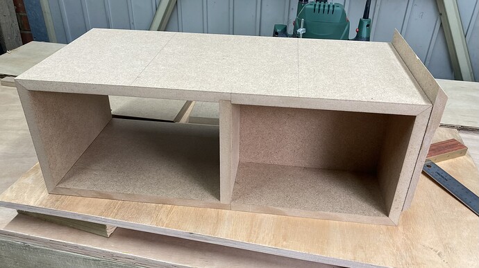
Gluing one side, the top and internal panels.

Left it over night and after I removed the clamps and started setting up the other side panel and bottom for glueing I couldn’t get them to line up nicely, the glued panels were slightly off square :confused:

Those corner clamps that I thought would be good for this really weren’t… they’re terrible in fact. They’d pushed up the top panel slightly, and the midrange panel with it. Maybe if I’d clamped the midrange panel vertically it would’ve been ok, but I didn’t intend to use them again.

So I had to remake all the panels! This wasn’t that bad really, the process was fresh in my mind, I’d worked out good ways to setup for cutting and I had the router guide offsets etc. Took less than a day in the end.

6 Likes

Glueing just the side and top panel this time, triple checking it was square.

Followed by the brace and midrange panel, and finally the other side and bottom panels. Leaving them a long time in between so the glue had really set.

Nice and square now.


The piece of wood on the side was held on with double sided tape … just because I needed another pair of hands while clamping, amazing how hard this was to get off!

8 Likes

Jumping ahead to the front panels, seems I didn’t take pictures until this point.

Tweeter hole routed on the inner front panel and the midrange and bass on the front outer panel.

Chamfering the back of the mid and bass driver holes.

Transferring the chamfered hole diameters to the inner front panel.

Mid and bass driver holes cut and also chamfered.

The two panels together from the front …

And the back. The chamfering is done to allow the drivers to breathe (see the measuring tests on Troels’s site to see the difference this makes)

Ready to glue the front panels on.

18 Likes

Very tidy work! Well done. Just a shame you didn’t build the lower half of the box, you’d be pretty much done already!

2 Likes